Friday, March 20, 2015

Making of a Miniature, Part 1


So now that my designs are out in the wild (check this thread if you haven’t yet! ) and I wanted to give the community an idea on how the miniature design process works for me.  It varies from designer to designer, and from digital sculpting to traditional sculpting, but this is how I do it.

Now I want to start this off by saying that I am not an artist or even a CAD designer by trade.  I work my day job as a computer engineer and happened to pick up CAD work as part of an internship about four years ago.  Throughout the last few years I have worked in it on the side, but I really didn't do anything significant until the last year or so, when I made a Vulture III and a Thor II last winter.

Now I use Autodesk Inventor.  It is a mechanical CAD  program.  I know other designers use Dassault Solidworks (a Mechanical CAD), Autodesk Maya (a CAD program aimed at animation and video games) and Pixologic ZBrush (also an animation CAD).  Essentially, you have CAD that is for designing parts and CAD for computer graphics.  I come from the part design world.  My experience is in both Dassault CATIA and Autodesk inventor.  CATIA is an extremely high end software, which also makes it prohibitively expensive.  Inventor is free for anyone with a .edu email address, and since I am still taking master’s courses, it fits me perfectly, free.

Now because I work in mechanical CAD, rather than a Mesh or Node editor CAD, the way that I design my miniatures is different from how some of my colleagues may.  I start with 2D sketches and push and pull them into 3 dimensional objects.  Now, if you want an in-depth look at that exact kind of thing, take a look at my personal blog posts on designing the Thor II: http://randominterestsofanaverageman.blogspot.com/2014/02/the-making-of-model-part-1.html. 

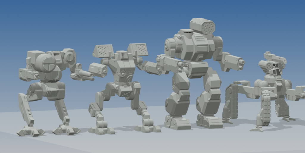
Now I have worked on four miniatures for IWM (5 if you include my not-accepted Vulture III), and they are a bit of a hodge-podge.  Thor II. Arctic Wolf II. Arion. Chimera.  Typically, IWM plans what minis they want to produce for the year, and then assign sculptors to work on them and get them released.  Anything that is not put on the schedule is added as an online exclusive.  So when I completed both the Thor and the Vulture, they were slated to be online exclusives.  Part of the reason for this also is that my CAD style hasn’t been perfected yet, and some designs, curvier designs, are still difficult for me to capture properly.

Moving on.

So now you know what software I use and why most of my work is Online Exclusives, so let’s talk about the designs I work with and the QCC process.

First things first, I pick a ‘Mech.  We all know what IWM’s release schedule is for the year, and what ‘Mechs have already been made, so I immediately remove them from my list of possible choices.  From there, I pick a ‘Mech that fits my CAD style.  Something a little blockier.  My first attempt was the Vulture III.  Very blocky, very geometric.  No smooth curves, no difficult to model surfaces.  The Thor II was also a solid choice in this respect.  The Arion also fit this style of mine, though to a lesser degree, and because of this, I hit a few snags, which I may or may not cover later.

Now, I also love Mechwarrior 4.  It is what got me into Battletech, got me into Miniatures, and started the downward spiral I call a hobby.  This game has also directed some of my designs here and it is the reason I chose both the Arctic Wolf II and the Chimera to work on.  The Arctic Wolf also happened not to have a miniature yet, and there definitely are some people looking forward to this mini.  The Chimera on the other hand, well, I just did not like the existing mini.  Tiny legs with a huge body, and a lot of the details I just felt were off.  So, I decided to take a crack at resculpting it.

Now, when I went into the Vulture and the Thor initially, I had no intention of doing alternate configs.  But when I always finishing the Thor, I saw the Dark Age mini, and saw the stats, and decided to make the missile box arms also.  From there, I have decided to make alt configs for all of my minis when they are available.  Meaning, if there is a reasonable alt config, my minis will probably include one of them at least.  We’ll go into more details on those when we start talking about the full QCC process, probably in part 2.


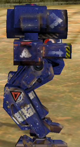
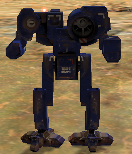
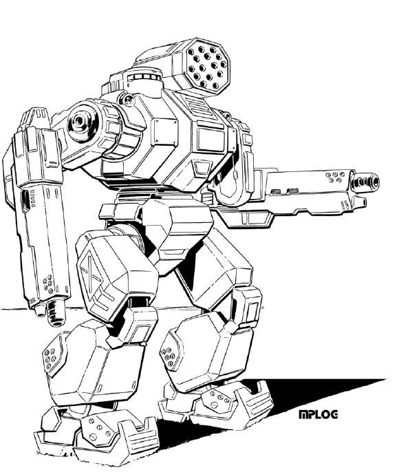
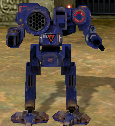
Typically, for CAD designers, we start making the entire miniature, but without any details on it.  We want to decide on the height of the mini, and make sure the basic proportions are dead on.  I will be using the Chimera as my example here.  I gathered as much source art as physically possible, which really isn’t much at all.  There is the TRO image, and luckily, this is a ‘Mech from Mechwarrior 4.  Even better yet, it was designed for Mechwarrior 4 and put into TRO: 3067 after that game was released.  So, I hopped into the game a took a few screenshots:

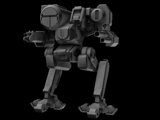
Also, I found an image from the Battletech Pods to use as a reference, this piece of art right here, which also conveniently lined up really good with the source art:


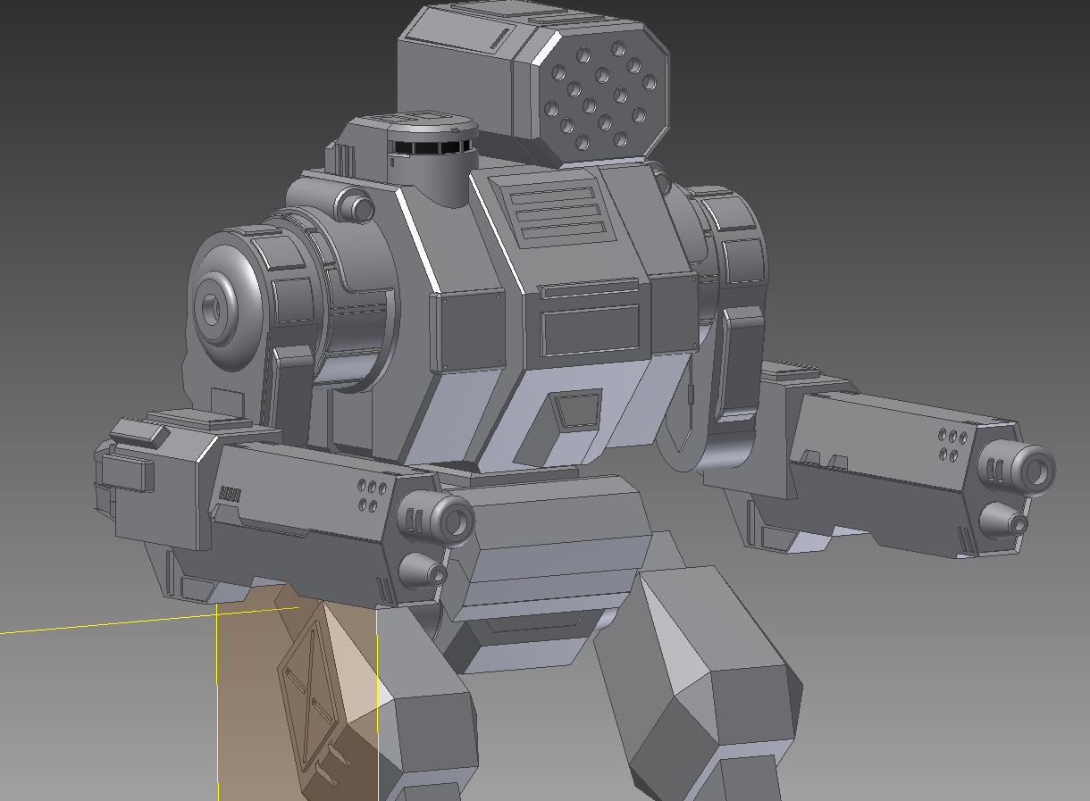
From there, I made my first run at the basic shape of the mini, check it out:
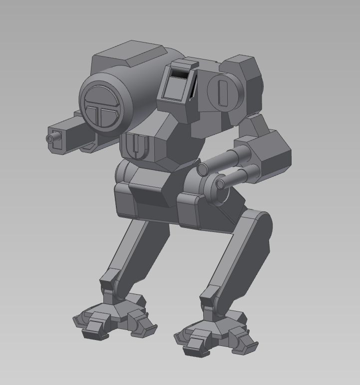


This is what I showed IWM when I asked if they wanted to resculpt the mini, and it is what was first submitted to the quality forum for my peers to review. You can quite obviously tell that there are some issues with this block out.  Small legs are the immediate issue, but there are more.  The IWM quality forum helped me get rid of some of these problems.


What did they have to say? Well, that will have to wait for part 2…

Friday, May 16, 2014

Installing X-Wing and TIE Fighter Collectors Editions, Legally!


So, there has been a lot of talk on the internet about installing the old X-Wing and TIE Fighter PC games.  So I thought I would post a guide on how to install the games (mostly) legally.

Recently, the Internet Archive released a library of pack-in and demo disks.  After searching through it, I found that both X-Wing and TIE Fighter Collectors editions were included, and these were the good ones, the DOS/Win 95 packs.  Take a look at the CD Archive here. Both X-Wing Collectors Edition and TIE Fighter Collectors Edition were included.  The download links are on the left hand side of the screen.

The Internet Archive has long been a reputable site, so I wouldn't worry about the legality of these files.  The have plenty of opportunity to take them down and these files are available publicly.

Once you have downloaded the .iso file for each disc, move them to a folder on your PC somewhere near the root of your drive.  I like to create a folder C:\OLDGAMES, and then create a subfolder called ISO.  Copy your .iso files there.

Now, we need DOSBox.  If you are on windows, check out this link to download.  If you are on Mac OS or Linux, just check out the DOSBox website.  Once installed, open the program and you get a nice DOS Prompt.

I don't have access to my main PC right now, so we will have to do without screenshots until I can update this later.

Open dosbox, and enter the following commands:

     mount C: C:\OLDGAMES
     imgmount D: C:\OLDGAMES\ISO\XWINGCD.iso -t iso -fs iso

To Install the game, now type these commands:

     D:\
     setup  (it may be install, but I am not complete sure, will update later)

Follow the standard install, make sure to test the audio and set the soundcard to a SoundBlaster 16, as this is DOSBox's default.

Now everything should be installed, so let's play!

Type:
     C:
     cd xwingcd
     xwing  (might be xwingcd)

And you are set!  You can  play with keyboard and mouse or a joystick, and that joystick should be automatically detected by DOSBox.

Now, whenever you want to play, open dosbox, and enter these commands:

     mount C: C:\OLDGAMES
     imgmount D: C:\OLDGAMES\ISO\XWINGCD.iso -t iso -fs iso
     C:
     cd xwingcd
     xwing  (might be xwingcd)

If you want to play full screen, make sure to press ctrl+enter.  To exit, exit through the games menus and then type exit at the DOS Prompt.


Now, TIE Fighter sometimes has joystick issues, so there is a patch out there to fix that.  Its is available from Lucasarts I believe.  Download that patch, dump it in the C:\OLDGAMES\TIECD folder, and then run it from the dos prompt.  Should fix any issues.

Make sure you leave any questions/comments in the comments section!

Monday, May 12, 2014

A Morning Sunrise


It is a strange world we live in today.


Though given this beautiful world, many choose to escape it.  To enter into our own little (mostly digital) worlds, and hide away from that which is happening around us.

Now, don't take me wrong, I do this same thing myself time and time again. Just take a look at this Blog and you will see how obvious that is.

But on my drive in to work this morning, I was lucky to catch my favorite part of the sunrise.  The official sunrise time for this morning was 6:13.  But around half an hour before sunrise, on mornings with some clouds in the sky, the sun lights the clouds from below, instead of above.  

This creates some beautiful crimson reds, that spread only on the tips of the ridges of the clouds, as if someone has taken a brush and grazed a thing layer of paint over those edges.

Further down the horizon, before we even reach the clouds is a brilliant pool of red and orange light, the pot from which the brush is dipped.  

To the left, on this particular day, the cool white light of the moon perforates the clouds, lending to an odd mixture of warm and cold light that will be washed away by the coming sun.

Not my photo, but pretty much what I was inspired by.  Mine photo had a lot more blur, cars, and power lines in the way.

It is in times like these, scenes like these, that I take a second to look at the world God has given us.  The world that we have been blessed with.  It is a reminder that there is so much more than our little worlds we build for ourselves.  So much more than the here and now.

As I look out onto this beautiful scene, I say a silent prayer thanking the Lord for my life and everything and everyone in it.

Wednesday, February 12, 2014

Update on Model

 Okay, so long post like I had before are quite time consuming, and then I got focused on making the model, and playing some games, and school work, and well, everything.  So blog posts went by the wayside.  With that, I want to make a quick update on the state of the model.  I have the entire upper half complete.

I just finished the hips today and have a start of the legs, though they may not be bulky enough at this point in time.  Also, the head seems a bit small and the arms seem a bit big.  If anyone has any opinions, they would be greatly appreciated.

Lastly, I want to mention that this is actually my second modeling project and my first is actually in review with Iron Wind Metals right now, so I have already been in contacted with the original artist, Matt Plog.  So I will also be reviewing the model with him when I am done.

Without further ado, here is the model at 65% complete :) 

Saturday, February 8, 2014

The Great Monitor Upgrade

So this is going to have a completely unnecessary analysis of monitors.  Beware.

I am going to be upgrading my PC monitor and graphics card soon, I have been debating for quite a while which setup I am going to use:  a 21:9 29" monitor or 3 20" standard widescreen monitors.

There are quite a few factors, such as Resolution, screen area, screen height, and price.

So, first, the competitors: three HP 20xis vs an AOC Q2963PM. 
(I can't get blogger to put these side by side)

The 20xi is currently priced at $99.99 while the Q2963PM is $379.99, making the triple HPs a better deal by over $80, but there are some issues with this.  Namely, resolution.

Each 20xi has a resolution of 1600x900, making three of them a total of 4800x900, or about 4.3 Megapixels at an aspect ratio of 16:3.  The Q2963PM has a resolution of 2560x1080, or 2.75 Megapixels, at an aspect ratio of 21:9, or 7:3. Lower resolutions equal lower necessary graphics power.  Lower graphics power means cheaper card when I buy it for upgrades.  The more expensive required graphics card nullifies the cheaper monitors pretty much off the bat.  I can get a GTX 760 for around $235, which would work great for the 21:9 screen, but I would probably need a more powerful GTX 770 for the triple monitor setup. If I were to bump up to bigger screens, like a 23xi, with a resolution of 1920x1080, I simply would not have enough horsepower to run games at 5760x1080, which is nearly 6 Megapixels.  

Now, screen area.  A nice website I have found for comparing screen area is Display Wars.  They provide some very nice comparisons of screens along with all of the numbers, so you don't have to calculate them yourself.  Look here for the comparison of the two screen sizes.  We can see that the 21:9 screen has an area of 304.5 sq. in. while the 20xi has an area of 170.9 sq. in.  This makes a single 21:9 screen have the same area as about 1.75 20xis.  Not bad, but cost wise, not good either.  The 21:9 is not looking like a good bang for my buck.

Now, a concern brought up to me out on the HardOCP forums was vertical height.  And I thought to myself, yeah, that makes sense.  The smaller screens are going to have less vertical height and it won't be as good for gaming.  But in looking closer at the displaywars numbers, I notice the stats.  20xi height: 9.81 inches.  Q2963PM height: 11.42 inches.  A difference of only 1.61 inches.  Now it is looking like a lot less that I originally envisioned.  1.61 inches, about 4 centimeters.  Can it make that much of a difference?

Finally, there is the inherent advantage of having a single large screen over several smaller ones.  Videos on youtube can be 1080P.  Games that can only run on 1 screen look better.  Better for things such as CAD work or even document writing sometimes.

My final consideration is mounting my original monitor above the 3 20xis, but I don't know if this is possible.

I will be buying in a month or two, so I have some time to decide...

Tuesday, February 4, 2014

The Making of a Model Part 2

The Making of a Model Part 2


Okay, I left off yesterday with the shoulders, and lets just jump right into it.

First off, we are going to make a quick circular sketch on the right side flat part.  Like so:


We extrude it out, and lets see how it looks:


It looks good.  Now lets cut some grooves into that circle to give the appearance of that armored look, with several panels like it has.  We’ll do 12 panels, to make it look like the art, but we may need to adjust later.

First, the sketch:


Then the groove:


Then the rotational pattern to make 12 of them:


Looking good.  We’ll need to make a few detail oriented changes to match the art.  I won’t go in depth on these, as it will take me 200 words to go over something that won’t seem to make much of a difference.

The real key is though, that these small differences are still important.  It is the small details that make a good model a great model.  That will make something worthy of a 3D printer.  So take a look at my changes:


These small changes add realism to the model that wasn’t there before.  The corners of each armor panel are now rounded, while the edges are now slanted over (chamfer, for those who know CAD).  I bumped out the center the shoulder slightly to accommodate better joint with the arm.

Now I am going to make the shoulder cowl, and we will begin on the laser mount above it.  I switch to wireframe view to get a better view of what is going on.


From there, I extrude, about 2.5mm, where the whole shoulder assembly was about 3mm.  This leaves just a little of those armor plates exposed, giving some nice detail.


Lastly, I round over the corners and the edges to match the artwork.


Next, it is time to work on those shoulder lasers.  Each shoulder has a medium laser on top of it, with a housing around it and a lens in the middle.  These are going to be a little tough to model, but if I use one of the origin planes to create the housing, it shouldn’t be too tough.
First, the sketch:


Then the extrusion:


And finally, the details which would have taken too long to explain:


Now, I am going to try and add some details which were not immediately visible in the original art, but may add some more character and “roboticness” to the ‘Mech.  I am going to try and add power cables to the back of the lasers.  I am not going to explain what I am going to do, I am just going to do it, and I’ll explain after pictures:


That turned out much better than expected.  We could call this section the power coupling and cooling jacket for the laser.  Either way, it adds a nice bit of detail where there really wasn’t any of the original picture.  A glance at the back of the original Dark Age miniature doesn’t have this, but I think it adds something to the ‘Mech, so I am going to leave it.


I think that is all I am going to blog about today.  I will be making a few more additions along with some detail for the back, and we’ll get to the head and missile launcher tomorrow!

Monday, February 3, 2014

The Making of a Model Part 1

Okay, so I am going to try and post about modeling in CAD and maybe give a step-by-step on how I did it.

This is going to be a bit over-detailed, but I will get less detailed as steps continue and my thought processes become more transparent.

So first, the source:


This 'Mech is a Thor II from BattleTech Technical Readout 3145: Clans.  It was originally based of a miniature from MechWarrior Dark age, and then adapted to BattleTech just a few months ago.  There is no current BattleTech scale miniature of this machine, so I hope to model it and then submit it.  Let's see how it goes!

As you can see, this 'Mech has almost no curvy features beyond a simple circle here and there.  Everything is very geometric with lots of flat sides.  This is good, as it fits my CAD style quite nicely.  I am not good with the curvy features, and will probably never model something with such until I get a bit more training.

I am going to start with the center torso.  Most ‘Mechs from the BattleTech universe are divided into several parts: Center Torso, Side Torsos, Arms, Legs.  You will see this model (and most of the art) follow the same format, which makes logical points to design a model off of.  Starting in the center also creates a good point from which to build all of the features.
Now I am going to be extremely detail oriented in this model, and I hope to submit it to be made into a miniature, so every line, bump, or small detail you see in that image above will most likely be making it onto the model.  I also will be drawing some details form the original MechWarrior Dark Age miniature, seen below.


For modeling, I use Autodesk Inventor.  It is a relatively powerful CAD program, though not as powerful as some, such as CATIA or Unigraphics.  I originally learned on CATIA, but due to the high cost of owning even a student version, I haven't used it outside of a work or school environment.  Inventor is free for anyone with a .edu email address, and seeing that I am a masters student, it is an excellent opportunity to use this awesome and free software.  Even better, when I am done with school, I have the option of purchasing a perpetual license for the software for around $150, which is a steal.

Enough with the details, lets get down the the model!

Let’s begin:

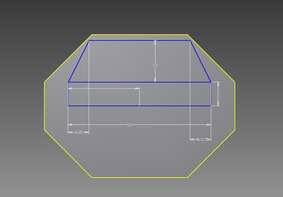
First, I start out with a simple trapezoid.  The center torso gives me the feeling it is a simple octagon, but I will be making half of it then mirroring it.  To simplify the process.
The basic sketch includes some basic, arbitrary measurements, but they serve for proportions.  Final measurements will be scaled up or down from these measurements.


Now I extrude it.  I make it a bit less than half the overall length.


And now I mirror it to make the full octagon.


Looking at this image and comparing it to the center of the original image shows me the shape is too wide and the center flat part is not tall enough.  Let’s adjust.


I doubled the height of the center flat bit, and that made everything seem more proportioned.  It is not perfect, but it is a solid start.  I may need to bump up the width later, or make further adjustments.  We’ll see.

Now, I am going to make one of the side torsos.  There is no point in making both of them because they are both symmetrical.  It really smoothes out the design when I can mirror almost any detail over to the other side.  The only thing that can’t be done via mirror is the top missile launcher and the head, both of which are no big deal.  Moving on…

The side torsos take the same shape as the center, just smaller, so lets do it!

Here is the initial sketch:


And now the extrusion:


And the first mirror:


And the second mirror:


And we see that there are some things off with the model.  I am going to reduce some sizes.  The flat parts in the front are currently 4mm tall, I am going to reduce that to 3.  Same with the wide of the side torsos, also to 3 mm.  Lets see what it looks like after adjustment:


There, much better.

Now lets add some of that center torso detail.  I will be making most of the detail on the right side of things and then mirroring it to the left.  For most of the center stuff, I won’t need to do that.

So, I won’t post the gritty details, but lets see what we can do.


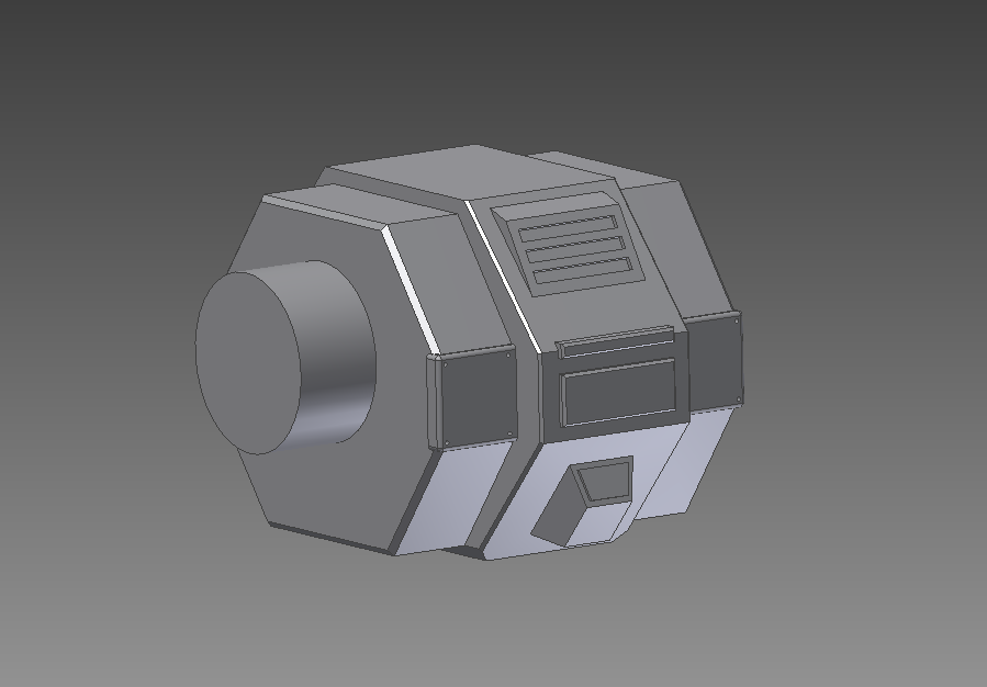
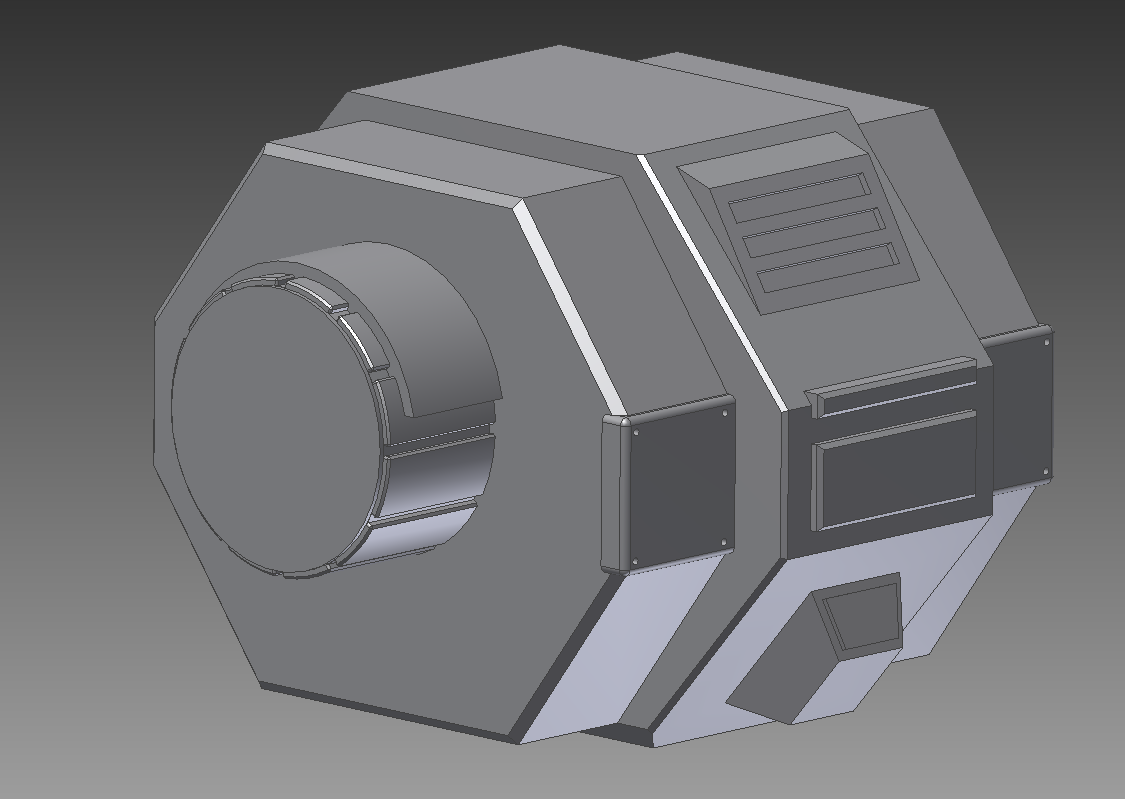
So I have added quite a few of the main details from the drawing onto my model.  This all in all took me about half an hour to do, but it overall shows that the details can be added in a 
simple fashion.  There were also a few mirrors involved, mainly with the end-caps (I don’t 
know what else to call them) on the left and right torsos.

Now I will move onto the “Shoulders”, if they can be called that.  These present an interesting challenge because of their various details, such as the “cowl” on the upper part of the shoulder or the pattern of gaps on the arms also.

Once the shoulders are in place, I can also create the lasers on top of the shoulders and the details below them. 

It is of important note that this whole process took me a little more than an hour and a quarter, including taking the screenshots and writing this up.

But that will be for next time…